
 Deutsch
FAQ - Questions and answers
General
For many of the items we offer, the operating instructions and, where applicable, data sheets, installation or assembly instructions are already stored directly with the respective item.
Select the desired item and click on the ‘Downloads’ tab below the images to view the available instructions.
If the ‘Downloads’ tab does not appear, unfortunately no instructions are currently available for the product. In this case, we will be happy to send you the instructions directly by email.
The purchase costs for underfloor heating depend on various factors. For example, the size of the area to be heated, the selected heating system and the type of floor covering are decisive criteria.
These three different variants are among the most common heating systems for underfloor heating:
-
Wet system underfloor heating
With wet system underfloor heating, pipes for a water-borne heating system are laid directly in the screed. This variant is usually only considered for new buildings, as laying the screed is quite time-consuming. Between 50€ and 80€ per square metre can be calculated for the purchase.
-
Dry system underfloor heating
Dry system underfloor heating is often used for renovations. In this case, dimpled profiles or special insulating panels are first applied to the existing subfloor, in which the pipes for a water-guided heating system find their place. The purchase costs for such a system are also around 50€ to 80€ per square metre.
-
Electric underfloor heating
With costs between 20€ and 50€ per square metre, electric underfloor heating systems are a favourable alternative. Especially since these systems are equally suitable for new and existing buildings. Installation is also much easier compared to the aforementioned heating systems.
Electric underfloor heating, whether made with heating films or heating mats, is completely maintenance-free. After a successful installation, you therefore no longer have any expenses or maintenance costs.
Whether a floor covering is suitable for underfloor heating depends on the thickness of the material and its thermal conductivity. The thermal resistance can be determined from these two factors. First, it is necessary to convert the thickness (d) of the material into metres. Then this value is divided by the thermal conductivity (λ) to obtain the thermal resistance (R).
The calculation formula is therefore R=d/λ.
For a floor covering to be suitable for underfloor heating, the thermal resistance of 0.15 m²K/W must not be exceeded.
Below are some reference values:
| Material | Strength | Thermal resistance |
| Laminate | 9 mm | 0,044 m²K/W |
| Parquet | 8 mm | 0,038 m²K/W |
| Cork (on backing) | 11 mm | 0,129 m²K/W |
| Vinyl (on backing) | 7 mm | 0,016 m²K/W |
| Design floor | 4 mm | 0,032 m²K/W |
| PVC | 2 mm | 0,010 m²K/W |
| Linoleum | 3 mm | 0,017 m²K/W |
| Natural stone | 20 mm | 0,017 m²K/W |
| Ceramic tiles | 13 mm | 0,012 m²K/W |
| Fine stoneware | 10 mm | 0,010 m²K/W |
| Carpet | 8 mm | 0,010 m²K/W |
| Nadelvlies | 7 mm | 0,012 m²K/W |
** These are only indications. Please refer to the data sheet of your desired floor covering for the exact specifications.
Heating with electricity is only expensive if electricity is used to heat the air. The infrared heating foil works on the principle of radiant heat and dispenses with the bad heat transfer medium - air.
The following manufacturers offer floor coverings that are also approved for use on electric heating systems. Please note that not every floor covering from the following manufacturers is suitable and you must obtain the corresponding approval.
- Meister / MeisterWerke Schulte GmbH
- Haro / Hamburger Flooring GmbH & Co. KG
- Wineo / Windmöller GmbH (wineo 600 Rigid, wineo 800, wineo 700)
- Objectflor / Objectflor Art und Design Belags GmbH
- Project Floors GmbH
- Arbiton Floor Expert (Amaron Superiore, Amaron Wood)
- ter Hürne GmbH & Co. KG (Avatara PERFORM, dureco Boden, Hywood Collection)
- tilo GmbH (tilo Fertigparkett und tilo Fertigböden)
- PiLiPP Holzwerkstoffe / Pilipp Vertriebsgesellschaft für Sperrholz und Bauelemente mbH
- KWG Kork / KWG Wolfgang Gärtner GmbH (JAVA Mineraldesign)
- EGGER Holzwerkstoffe Brilon GmbH & Co. KG
- COREtec Floors (Sound Core, Pro Core, Mineral Core)
The maximum thermal resistance of the floor covering must not exceed the value Rλ = 0.15 m2K/W. Often, only the thermal conductivity value is specified for floor coverings. To calculate the thermal resistance from this, the material thickness of the floor covering must first be converted into metres (m) and then multiplied by the thermal conductivity value.
Underfloor heating not only heats the floor, but also provides a pleasant, comfortable room climate. Due to the large surface area of the heating, a room is heated quickly and efficiently.
In addition, heating is not only provided in a specific area of the room, but is distributed evenly throughout the room. This results in significantly less air circulation and, above all, an even heat throughout the room. As a result, the whirling up of dust is minimised and at the same time the risk of mould formation is reduced.
Another advantage is that you do not waste space in the room with underfloor heating. The entire living space is retained and you can design it individually. In addition, heating costs can be saved with underfloor heating compared to conventional convection heating systems.
In principle, you do not need any in-depth specialist knowledge to install infrared heating foil or heating mats. However, the installation on the 220V mains must be carried out by a qualified electrician.
All electrical heating sources such as heating cables, heating mats, heating foils, heating fabrics, aluminium heating mats etc. that can be used as floor heating must be thermally monitored and controlled. This must be done by means of an external sensor (also called a floor sensor). Only in this way can a desired floor temperature be set constantly and the maximum temperature required by the floor covering manufacturer be maintained.
In addition to a normal fuse, the electrical supply line must also be protected by a RCD.
We attach great importance to individual advice and customer-oriented service. We therefore offer you project planning completely free of charge and without obligation.
Electric underfloor heating is a heating system that lays heating cables, heating mats or heating films under the floor covering to provide even heat to the room. These systems are connected directly to the mains supply and generate a pleasant, even heat that rises from the floor. Electric underfloor heating systems are not only space-saving, as they do not require visible radiators, but also energy-efficient, as they heat rooms quickly and precisely. They are suitable for both new builds and renovations and can be installed under various floor coverings such as tiles, laminate, vinyl or carpet.
Yes, electric underfloor heating systems are very efficient as they transfer heat directly to the room. Compared to conventional heating systems, they require lower operating temperatures to provide the desired level of comfort. While radiators often need to reach temperatures of 60°C or more, electric underfloor heating systems operate effectively at temperatures between 24°C and 29°C. These lower temperatures not only contribute to energy savings, but also improve comfort by ensuring even heat distribution and preventing the room from overheating. When used correctly and in well-insulated rooms, electric underfloor heating can help to significantly reduce energy costs while creating a cosy living environment.
Yes, the "normal" line is designed for 16 A (3680 Watt) load. However, it is important to consider how many consumers are connected to this circuit. If you want to lay out your entire house with infrared heating foil, it is recommended to provide individual fuses for the circuits. If you have any questions, an electrician should be consulted.
Heating film
The carbon heating film is on the rise. That is why there are currently low-voltage versions on the market, 12/24/36/42/48V and the 230V version for our mains supply. There are two principles of construction, the striped version and the full-surface version.
The most common widths of the heating strips are 50, 80 and 100cm but 25, 30, 43, 60 etc. are also in circulation.
The power consumption is mostly given for one m².
We carry the carbon heating film in 80, 100, 130, 160, 220, 400, 500Watt/m² and more in our assortment.
The infrared heating foil can be laid as a full-fledged heater on the entire floor * or on the ceiling.
* Only under furnishings that are at least 7cm above the floor. Such as. A bed on feet / stilts. ONLY the full-surface carbon heating foil may be laid under fixed furnishings.
The infrared heating foil is mainly installed as a supplement to the existing heating system in order to use the pleasant infrared heat in certain areas.
For laminate, parquet and vinyl floors with a backing board, you can use a laminated / reflective underlayment with 3 or 5mm thickness.
For thin floor coverings such as PVC, carpet or vinyl without a backing board, use a laminated / reflective underlayment with 1.5mm thickness.
Please also observe the manufacturer's instructions for the selected floor covering.
- For thin vinyl floors without backing board or carpet flooring, we recommend a maximum output of 100W/m².
- For vinyl floors with backing board, wood or laminate flooring, we recommend a maximum output of 130W/m².
- For installation under concrete or tiles, a power of 160 to 220W/m² can be used.
Other factors such as room size, insulation and the number of exterior walls must be taken into account.
The warm-up time of the floor depends on:
- Floor material: concrete or wood
- Choice of impact sound insulation 1.5 / 3 / 5 mm
- Selected floor covering and its thickness
- Power of the infrared heating foil
The warm-up time can therefore range from a few minutes to an hour.
| Comfort | Premium | High End | |
| Insulation | 1-fold insulated | 2-fold insulated | 3-fold insulated |
| Installation height | 0,366mm | 0,388mm | 0,6mm |
| Heating surface per m² | active heating surface 74% |
active heating surface 86% |
active heating surface 96% |
| available Heating capacities |
60-130W (+-10%) | 80-130W (+-10%) |
120-200W (+-10%) |
| Suitability |
Vinyl without HDF core board Vinyl with HDF core board Laminate/parquet PVC/carpet |
Vinyl without HDF core board Vinyl with HDF core board Laminate/parquet PVC/carpet |
120W for floating floor coverings (except vinyl without HDF core board, PVC and carpet due to high dimensional stability of the heating films *1) 150-200W for wall or ceiling heating behind plasterboards |
| Recommended application | Underfloor heating | Underfloor heating | Wall or ceiling heating, underfloor heating *1 |
Yes, a kind of carrier layer such as Fermacell, OSB boards or Mi-board has to be laid over the heating film. This carrier layer has the function of mechanically protecting the carbon heating film and absorbing the infrared rays as a heat transfer medium and distributing the heat evenly. The thermal resistance of the entire structure has to be considered. This must not exceed a value of Rλ = 0.15 (m²K)/W.
When using perforated heating elements in tile adhesive or levelling compound, the RCD may trip prematurely. The drying time of the applied material must be taken into account. Increased moisture content can cause the RCD to trip. After an appropriate drying time, tripping should no longer occur.
Yes, all heating foils can be shortened to almost any length.
Often, a marking for shortening is printed on the heating film during production. This is an unheated area approximately 1.5 cm wide with a scissors symbol printed on it. The heating foil can be cut along this line with scissors. The exposed copper tracks must be insulated. Depending on the type of heating foil, it can also be cut between the parallel carbon heating tracks. The entire cut edge should be insulated securely and watertight using suitable insulating tape.
When installing heating films, some points must be observed:
-
Heating power of the film: For floor coverings made of carpet, PVC or vinyl without a backing plate, a maximum heating power of 100W/m² is permissible. Floor coverings made of vinyl with a HDF backing plate, laminate or parquet can tolerate a maximum heat output of 130W/m². It is important that the floor coverings are approved for use on underfloor heating systems.
-
Structure: A so-called heating film underlay should be laid under the heating film. This serves as insulation on the subfloor and can partially or even completely accommodate the connection cables of the heating films. A PE foil (AquaStop foil) should be laid over the heating films. This reduces the friction of the floating floor coverings on the heating film. It also provides additional protection against moisture penetration. The actual floor covering is then laid on the PE foil.
-
Heating film underlay: Here, too, the choice depends on the desired floor covering. A maximum of 1.5 mm thick heating film underlay may be laid under carpet, PVC or vinyl without a backing board. Underlays with a thickness of 3mm or 5mm can be used for vinyl with a backing board, laminate or parquet.
-
Installation: When laying, make sure that the individual strips of the heating films do not overlap. The connection cables must also not run directly over the heating films.
-
Objects: Make sure that no objects with a diameter of more than 6 cm are placed directly on the floor. Otherwise, heat could build up and damage the heating foils and/or the floor covering. Such objects should therefore be jacked up, e.g. with furniture feet at least 5cm high, so that the air can circulate freely.
-
Thermostat: The heating films may only be operated with a suitable thermostat with a floor sensor. The limiting temperature should be set to max. 27°C. The floor sensor should be installed in an empty pipe so that it can be easily replaced in the event of a defect. The floor sensor should also project at least 10cm onto or under one of the heating films so that the temperature can be correctly determined.
-
Check: It is important to check the heating films several times during the work. Therefore, measure the resistance of each individual heating film immediately before starting work, after laying on the heating film underlay and the PE foil, and after installing the floor covering. You will find corresponding test protocols for this in our instructions.
-
Laying plan: Draw up an exact installation plan of the heating films and the electrical connection cables. Keep the installation plan in a safe place and pass it on to the relevant person if there is a change of owner/tenant.
- No damp rooms: The 230V heating film must not be installed in damp rooms. There are special 24V heating films that may be used for this purpose.
Detailed and illustrated installation instructions with all work steps can be found here: https://infrarot-fussboden.de/mediafiles/PDF/BDA_Mi-Heat-Heizfolie-DE.pdf
Usually this is harmless as long as the damaged area is isolated. But beware: If the copper strip is defective or damaged, the film is no longer useful and must be disposed of. However, you can cut the film from the damaged spot and then of course use it again. Repairs and modifications may only be carried out by a qualified electrician.
For most heating films, it does not matter how it gets laid. The type designation should be read from above.
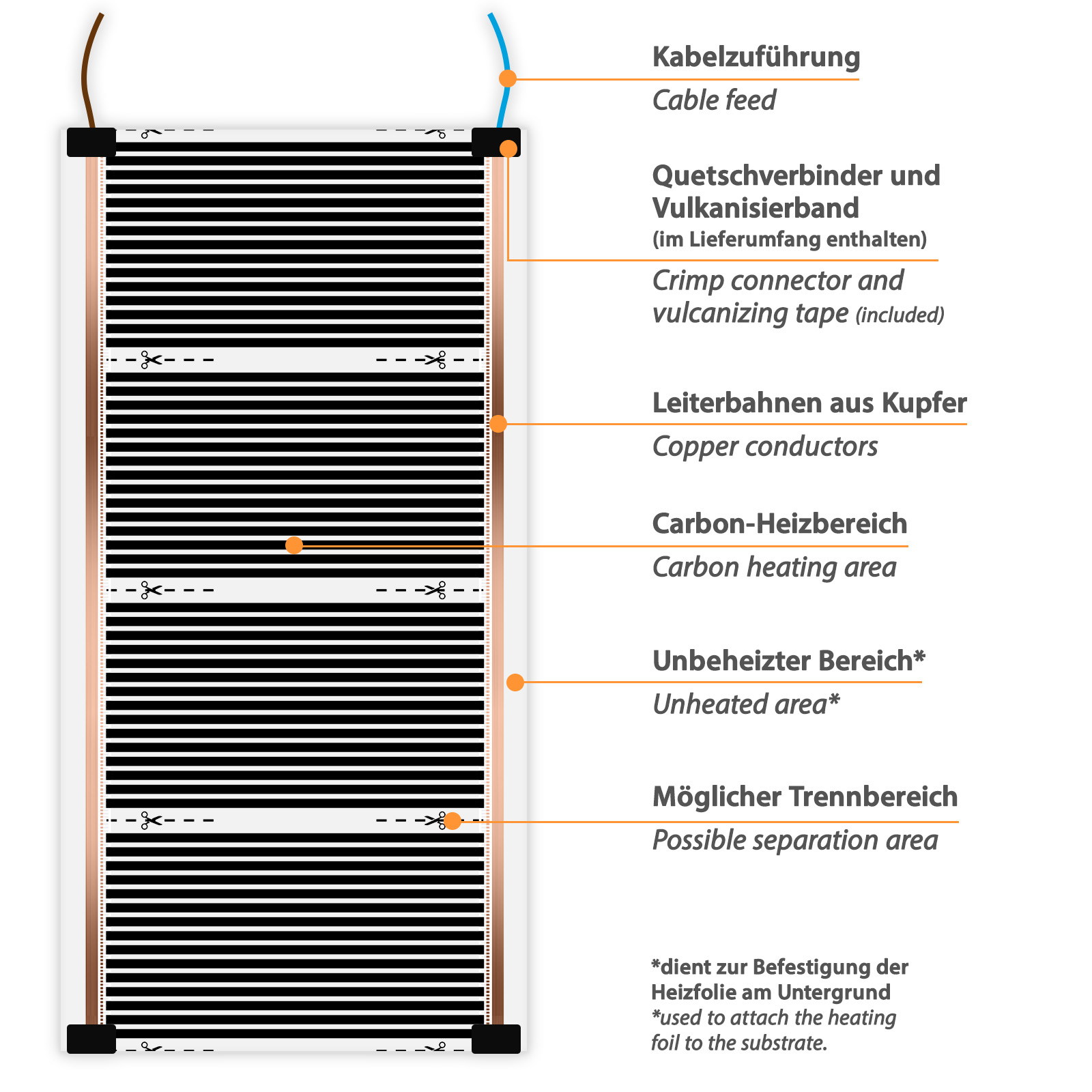
A heating film is the thinnest version of an electric heating source. Its low installation height makes it very popular for installation underneath the floor covering. The heating film heats up evenly and thus provides pleasant floor warmth over the entire installed surface.
- The outer copper tracks serve as conductors.
- Thin electrical wires conduct the current onto a carrier material. Depending on the heating film, this consists of carbon or graphite. The respective heating power of the heating film is determined by different mixing ratios.
- The heating film can be individually shortened to the desired length at the intended cutting points.
An infrared heating film for floor mounting should have a thickness of at least 0.3mm, otherwise it cannot withstand the pressure loads that occur. A thinner infrared heating foil is only suitable for ceiling mounting. A high-quality infrared heating foil has multiple insulation and robust copper tracks for current distribution. In addition, temperature-resistant and solvent-free adhesives are used. Our high quality standards enable a service life of up to 50 years.
Yes, Heating Film Underlayment has the following functions:
- levelling out unevenness
- additional thermal insulation
- impact sound reduction
- promotes upward radiation
- facilitates installation by allowing cables and connectors to be recessed/sunk.
In our shop you will find insulating underlays for common floor coverings such as laminate, parquet, vinyl on HDF or vinyl. The underlay/impact sound insulation must meet the requirements of the floor manufacturer.
All underlays offered by us meet the standards applicable in the EU with regard to compressive strength and fire behaviour.
The underlayment or also called insulating underlay, which is laid under the carbon heating film or also aluminium heating mats, does not have to be suitable for underfloor heating. This product specification refers to classic water-guided underfloor heating, where the impact sound insulation is supposed to let the heat through.
Our heating solutions, on the other hand, are laid directly on the underlayment and under the floor covering. This makes underlayment (not suitable for underfloor heating) the ideal component. These underlays have a much better insulation value and ensure that the heat is conducted upwards towards the floor covering as far as possible.
Yes. According to DIN VDE 0100-701, the provisions for protection zone 3 apply from an installation height of at least 2.25 m above the floor. In this area, neither safety extra-low voltage (SELV) nor an increased IP protection class is required. This means that Mi-Heat High End heating films can be used as ceiling heating in bathrooms in a safe manner that complies with standards.
The heating film may only be operated in conjunction with a suitable thermostat, which ensures thermal monitoring by means of an external sensor (floor sensor) and also enables the floor temperature to be limited to the maximum temperature specified by the floor covering manufacturer.
A resistance measurement with a multimeter already provides important information on the functionality and correctness of the heating film in question. When using several heating films, it is therefore crucial to test each foil individually. Before the measurement, heating films that are connected together (wired in parallel) must be disconnected in order to obtain reliable and meaningful measurement results.
Calculate current consumption and resistance
The High Power heating films offered may only be installed by a qualified electrician. The existing safety regulations must be observed. This product is primarily intended for industrial and commercial processing. The use of the articles by end users requires specialist electrical knowledge, especially in the field of electric heat. As a matter of principle, we (Mi-Heat Heizsysteme GmbH) accept no responsibility for the result of thermal processes during further use or processing of the product. This duty of care is borne by the customer himself. The product may only be operated with a thermostat.
We charge a flat-rate conversion fee in the following cases:
- In the case of a heating film web custom-made for the customer, which has a length deviating from the standard and for this reason must be electrically insulated over the complete web width.
- In case of a custom-made heating foil web for the customer, which is to be provided with a longer connection cable. The standard length of the connection cable per heating film track is 2.5 meters. The additionally required cable is also charged separately.
The installation of electric underfloor heating in showers without a tub (so-called floor-level showers) is generally permissible. Particular attention must be paid to the standards DIN VDE 0100-701 (low-voltage installations in rooms with bathtubs or showers) and DIN VDE 0700-96 (requirements for surface heating elements).
Consequently, there are two different heating systems that could potentially be considered:
- 230V heating mats and heating cables with earthing and IP67 protection (or higher)
- Low-voltage (SELV/PELV) heating films
Heating mats and heating cables are heating elements earthed (protection class 1) and waterproofed (at least protection class IP67) with a protective conductor braid, which are operated directly with 230V mains voltage. They can be installed either embedded in tile adhesive under tiles, porcelain stoneware or granite. Alternatively, a self-levelling levelling compound on which any floor covering can be laid is also possible.
Due to their design, heating films do not have a protective conductor (no protection class) and are therefore only permitted on a low-voltage basis (SELV or PELV) in damp rooms. The maximum operating voltage of the heating films is specified here by the DIN VDE 0100-701 standard, which designates showers without a tray as protection area 1. According to this standard, unearthed electrical floor heating systems with an operating voltage of up to 25V alternating voltage (AC) or up to 60V direct voltage (DC) may also be installed in a shower without a tray.
The low-voltage heating films are then again divided into two models: Low-voltage heating films with PET coating are intended for installation under floating floor coverings. Low-voltage heating films with a fleece lamination are suitable for glued floor coverings (e.g. design vinyl) or installation in tile adhesive or levelling compound.
Electric underfloor heating can also be installed under vinyl flooring. However, there are a few small things to consider.
In our blog article "Electric underfloor heating for vinyl: correct planning and installation" you will find all the information you need on the subject.
With low-voltage heating films, for example with 24V or 36V voltage, correct dimensioning of the transformer is extremely important. The easiest way to calculate is to first calculate the total area (m²) of the heating films and multiply it by their heating power per square metre (W/m²). This gives you the total power consumption (W) of the heating system. Now, it is important for a long life of the transformer not to load it permanently to 100 %. A buffer of 10 to 15 % should always be included in the calculation.
Calculation example:
Heating film 1: 24V heating film 60cm wide 150W/m² 1.5m long
Heating film 2: 24V heating film 87cm wide 150W/m² 2.5m long
Total area of heating films: Film 1 with 0.6m x 1.5m + Film 2 with 0.87m x 2.5m = 0.9m² + 2.175m² = 3.075m²
Total power of heating films = 3.075m² x 150W/m² = 461.25W
Required transformer power: = 461.25W + 15% = 530.44 W
We would like to give you some important tips on how to check the correct functioning of your heating film as electric underfloor heating in your caravan:
- The heating film is used to temper the floor and reduce the feeling of cold feet. However, it is not designed to significantly increase the room air temperature. An additional heat source (e.g. Webasto or Truma parking heater) is required to heat the living area sufficiently.
- When testing, be sure to cover the heating film with the floor covering or provisionally with cardboard or a blanket. As the system is based on the heat accumulation principle, a large proportion of the heat is lost without a cover.
- Carry out the test under realistic conditions: The vehicle should be preheated via an additional heat source. In a cold vehicle, the heating performance can be distorted, as the cold ambient air quickly absorbs the heat generated.
- Allow a lead time of approx. 20 to 40 minutes, depending on the ambient temperature.
- Use an infrared thermometer or a suitable measuring device instead of feeling the temperature with your hand. The palm of the hand often has a similar temperature to the heating film, making it difficult to perceive the heating.
- Make sure that the thermostat's floor sensor is approx. 10-15 cm inside the active heating area.
- Check whether the thermostat is set to ‘external sensor / floor sensor only’ mode. If necessary, adjust the floor limit temperature (recommended: max. 29 °C).
Tip: The use of a heating film underlay that matches the floor covering and is laid under the heating film as additional insulation can improve the efficiency of the heating film.
Heating cable / heating mats
The Snow Melting heating mats can melt up to 6 cm of snow per hour. In addition, the heating mats can also be placed on already formed ice to melt it.
Laying heating mats is extremely simple. We always deliver our heating mats as a roll, whereby the width is 50 cm and the length is correspondingly long depending on the selected square metres (m²).
You then simply roll out the heating mats and lay out strips. At the end of a strip, they cut through the backing fabric and fold the mat over. When doing this, make sure that the heating cable is not cut, kinked, crossed, shortened, crushed or damaged!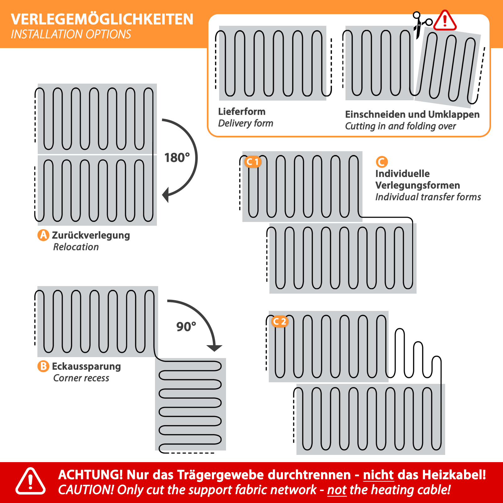
The resistance of each individual heating cable should be measured and documented with a multimeter before installation. For a short-term function test, the individual heating cables can be connected directly to the 230V mains. As soon as the cables heat up, however, they should be disconnected from the mains again. Permanent operation without thermostats is not permitted and can lead to damage.
After each heating cable has been measured and tested individually, they can be laid out and wired. It should be noted that the heating cables may only be connected in parallel and not in series. Afterwards, the total resistance across all heating cables should be measured again with the multimeter. A final function test by applying the mains voltage again is advisable.
After all steps have been carried out, grout or tile adhesive can be applied.
A newly laid tile covering still contains a lot of water, which must first evaporate. Therefore, the function of the underfloor heating is hardly noticeable during the first 14 days. In addition, the underfloor heating should only be put into operation after the tile adhesive has completely hardened (please follow the manufacturer's instructions).
Before installation, the resistance of each individual heating mat should first be measured with a multimeter and documented. For a functional test, the individual heating mats can also be connected directly to the 230V mains, i.e. without thermostats. As soon as the mats heat up, however, they should be disconnected from the mains again. Permanent operation without thermostats is not permitted and can damage the heating mats.
After each mat has been measured and tested individually, they can be laid out and wired. It should be noted that the heating mats may only be wired in parallel and not in series. Afterwards, the total resistance across all heating mats should be measured again with the multimeter. A final function test by applying the mains voltage again is advisable.
The Warmup company offers a germany-wide service for the localisation and repair of damaged areas on electric underfloor heating systems. Telephone: +49 (0) 4431/948700
The loop distance of the heating cable should be between 8cm and 12cm. If the loop spacing is too small, the heating energy per square metre is unnecessarily high. If, on the other hand, the loop spacing is too large, noticeable cold bridges can occur.
All our heating mats (thin-bed heating mats, aluminium heating mats, outdoor heating) and heating cables are tested ex works and their resistance value is noted on the type plate.
During installation, several resistance measurements should always be carried out in order to detect a possible defect at an early stage.
The first resistance measurement should be taken after delivery and before installation. In the corresponding operating instructions you will usually also find a corresponding test protocol in which you can note the resistance values. The next resistance measurement should be taken after the heating mats has been laid, but before the floor covering or tile adhesive / levelling compound is applied. The last resistance measurement should be carried out after successful installation of the floor covering.
We recommend always using the inexpensive Warmup Watchdog alarm detector for installation. This is mounted on the heating mats or heating cables for the entire installation process and continuously takes a resistance measurement. If damage occurs during installation, the Watchdog emits an acoustic warning signal. This gives you the opportunity to act early and repair the damage with the help of the heating cable repair kit. The Warmup Watchdog alarm can be removed after successful installation and reused as often as desired.
If you are not confident enough to carry out a repair yourself, you can make use of the services offered by Warmup. Warmup offers a germany-wide service for locating and repairing damaged areas on electrical heating systems. Telephone: 04431/948700
Heating mats, regardless of whether they are aluminium heating mats or thin-bed heating mats on carrier fabric, cannot generally be shortened. The reason for this is a change in resistance of the installed heating conductor and an associated change in power. For purely physical reasons, the formula P=U²/R results in a higher output with lower resistance.
However, if the residual amount in a thin-bed heating mat is reasonably small, the heating cable can be carefully detached from the support fabric and laid, for example, on a free edge surface in the room. It is important here that the individual loops of the heating cable must not touch or cross each other under any circumstances. The minimum distance of 5 cm must always be observed.
If you have an aluminium heating mat that is too large, please contact our support for an exchange.
Yes, but there are special, particularly robust heating mats in our range for this area of application. These ensure that you never again have to clear your driveway of ice and snow early in the morning. In addition, the risk of injury can be significantly reduced. With a suitable control system, the mats also do not heat continuously, but are only activated when there is a risk of snow and ice forming. You can find suitable outdoor heaters and controls in the "Deicing Systems" section of our online shop.
No, our heating mats have up to 3000W of power and should therefore not be permanently connected to a power socket. However, permanent wiring to the mains supply may only be carried out by a qualified electrician, as applicable VDE and EVU regulations must be observed.
The coloured connection cables (black, blue, green-yellow) can be lengthened or shortened as desired, as they are normal power cables. However, nothing may be changed on the heating wire, as the cable length is precisely calculated. Shortening or lengthening the heating wire would interfere with the function or may even cause damage.
Heated Carpet
No, office chairs with castors must not be used on the heating carpets. The point pressure load is very high and the constant movements would put a lot of mechanical stress on the heating conductors and could break them.
Yes, chairs and tables with legs may stand on the heating carpet. Only pieces of furniture with a large base may not stand on the heating carpet, as otherwise heat can build up.
Infrared heaters
To reset the TH400/TH600 towel heater to the factory settings, please proceed as follows:
- Switch off the unit
- After a few seconds, switch the unit on again
- Press and hold the "Timer" button on the touchscreen for at least 5 seconds
- A slowly flashing WLAN display confirms the successful reset
When the TH400 towel heater shows the abbreviation "BP" in the display, the unit is in the so-called bypass mode. This mode is intended for control via an external thermostat. Normal operation via the unit buttons or via smartphone app is not possible in bypass mode.
To exit bypass mode, press the + and - buttons simultaneously. The "BP" display then goes out accordingly.
If the process is repeated, the bypass mode can be activated again.
No, the infrared heating panels must not be installed directly or covered, as this may lead to a build-up of heat. Although a built-in temperature fuse protects the units from overheating, they should not be installed or covered under any circumstances.
Infrared heating panels are completely maintenance-free and do not require any maintenance measures. Occasional cleaning with a damp cloth is possible, but not necessary.
As a rule of thumb, about 60-80 watts of heating power are required per square metre (m²) of room area in a normally insulated living space. The calculation becomes even more precise when the room height is taken into account. The rule here is that an average of 30 watts of heating power is required per cubic metre (m³)
Thermostat
Please note the following information regarding the integration of the device into the Tuya Smart, Smart Life or Sundirect Smart app (depending on the device).
5 GHz Wi-Fi: The router you are using may provide a 5 GHz Wi-Fi network that is not compatible with this device. The device only works with 2.4 GHz Wi-Fi. However, with many routers that provide both 2.4 GHz and 5 GHz Wi-Fi networks, connection is still possible without any problems.
Wi-Fi 6: With the latest router models, the Wi-Fi 6 standard (IEEE 802.11ax) or Wi-Fi 7 standard (IEEE 802.11be) may also cause problems if the device does not support them.
Wi-Fi repeaters: If one or more Wi-Fi repeaters are being used, they must be disconnected from the mains before attempting to pair them.
Troubleshooting:
Routers with Wi-Fi 6 and/or Wi-Fi 7 standard
1. Where possible, switch the Wi-Fi 6/Wi-Fi 7 standard for 2.4GHz Wi-Fi – and, if available, for 5GHz Wi-Fi too – to Wi-Fi 5
2. Then try pairing the device again
3. If this does not work, you should also disable the 5GHz Wi-Fi
4. Try pairing the device again
5. Once the device has been successfully paired, the 5GHz Wi-Fi and Wi-Fi 6/Wi-Fi 7 can usually be re-enabled
Routers without the Wi-Fi 6 standard but with 5GHz Wi-Fi
1. Disable the 5GHz Wi-Fi
2. Then try pairing the device again
3. Once the device has been successfully paired, the 5GHz Wi-Fi can usually be re-enabled
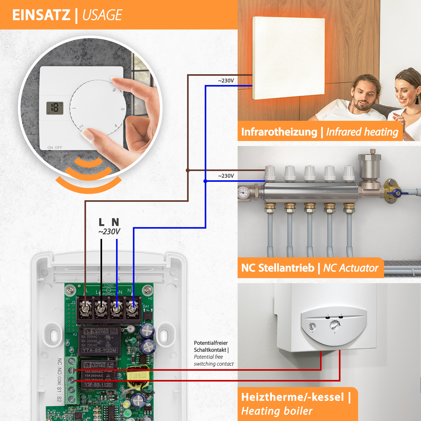
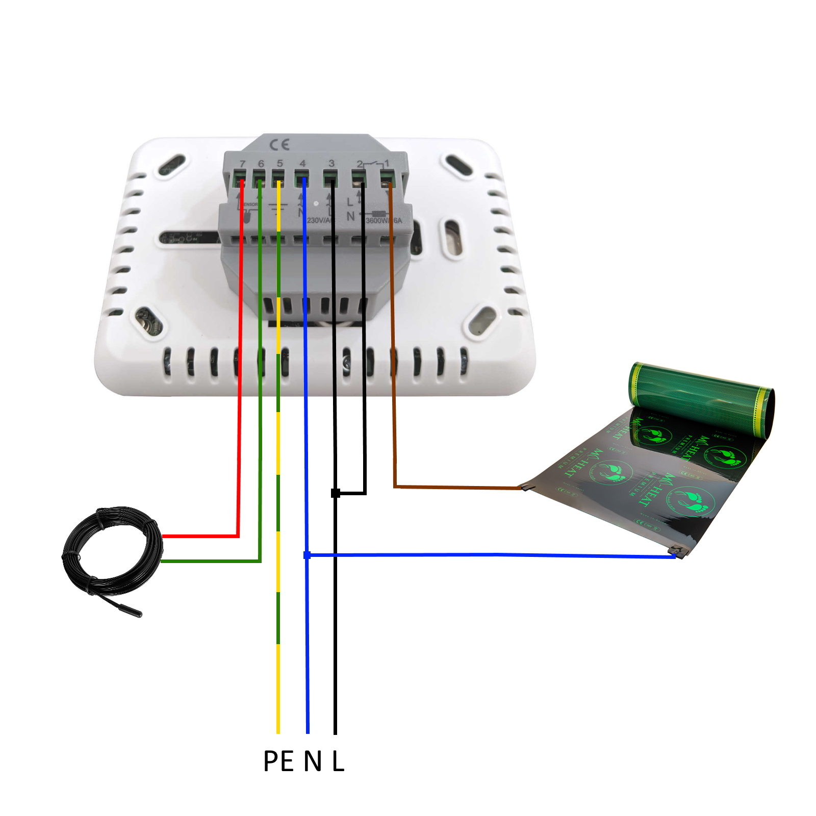
The SAS816RF remote thermostat has two separate switching contacts. Either 230V consumers (e.g. electric heaters or NC actuators of a water-guided underfloor heating system) can be switched directly via a load contact or a control signal (e.g. for boilers / heating systems) via a potential-free switching contact (COM / NO / NC) is possible.
The thermostats of the "O" series can be integrated into the Busch & Jäger Reflex SI and Jussi switch ranges. In the "M" series, the thermostats are manufactured in a 55 x 55 mm grid and can be integrated into the following switch ranges:
- Berker (S.1, B.1, B.3, B.7 Glass)
- GIRA (System 55, Standard 55, E2, E22, Event, Esprit)
- Merten (1-M, Atelier-M, M-Smart, M-Arc, M-Star, M-Plan)
- JUNG (A 500, AS 500, A plus, A creation)
- ELSO (Joy)
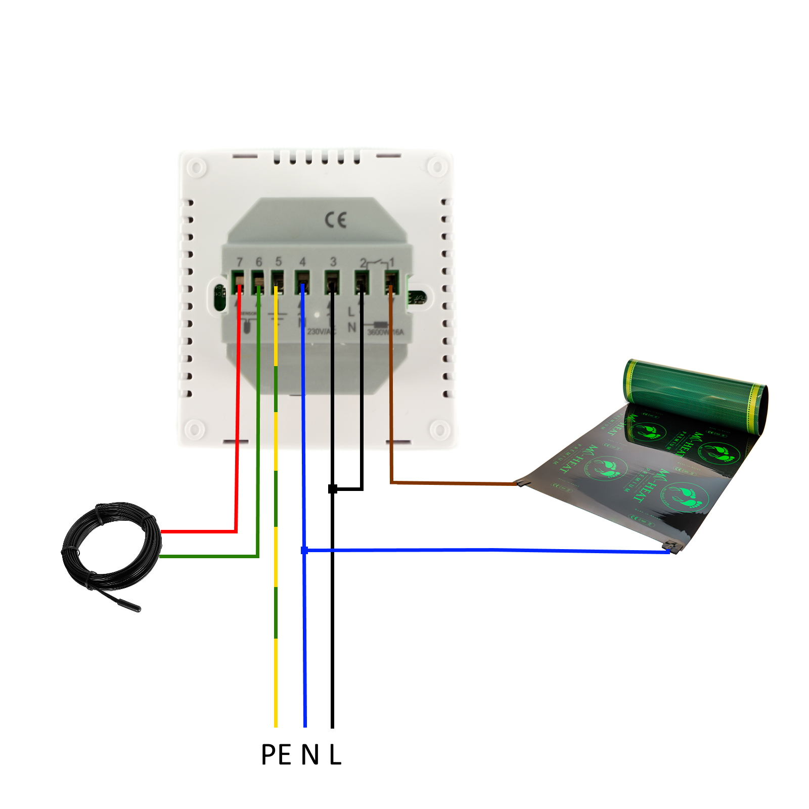
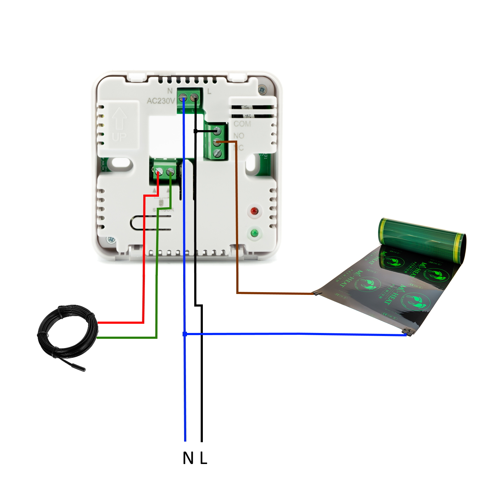
The Optima thermostats have a so-called potential-free switching contact, which initially does not output any voltage. It is therefore necessary to connect a bridge from the phase (L) to one terminal of the switching output. One connection line of the heating film / heating mat is then connected accordingly to the other terminal of the switching output. The other lead of the heating film / heating mat is connected directly to the neutral conductor (N).
Optima WLAN Classic TH08W Thermostat (Art.Nr. 1028)
Optima WLAN 7" Touch Thermostat (Art.Nr. 1031)
Optima WLAN Basic Thermostat (Art.Nr. 1027)
It is possible to restore the factory settings on the Mi-10 thermostat as follows:
- Switch off the power supply.
- Press and hold the up and down arrow keys simultaneously.
- While holding the buttons down, switch on the power supply. Continue to hold the buttons down for about 10 seconds.
- After you have held the buttons down for about 10 seconds, horizontal lines should appear on the display. The unit is reset.
The Mi-10 thermostats have a so-called potential-free switching contact, which initially does not output any voltage. It is therefore necessary to connect a bridge from the phase (L) at 230V AC or plus (+) at 12/24V DC to one terminal of the switching output. One connection wire of the heating film / heating mat is then connected accordingly to the other terminal of the switching output. The other connection wire of the heating film / heating mat is connected directly to the neutral conductor (N) at 230V AC or to minus (-) at 12/24V DC.

Mi-10 Thermostat 12V DC (Art.Nr. 603)
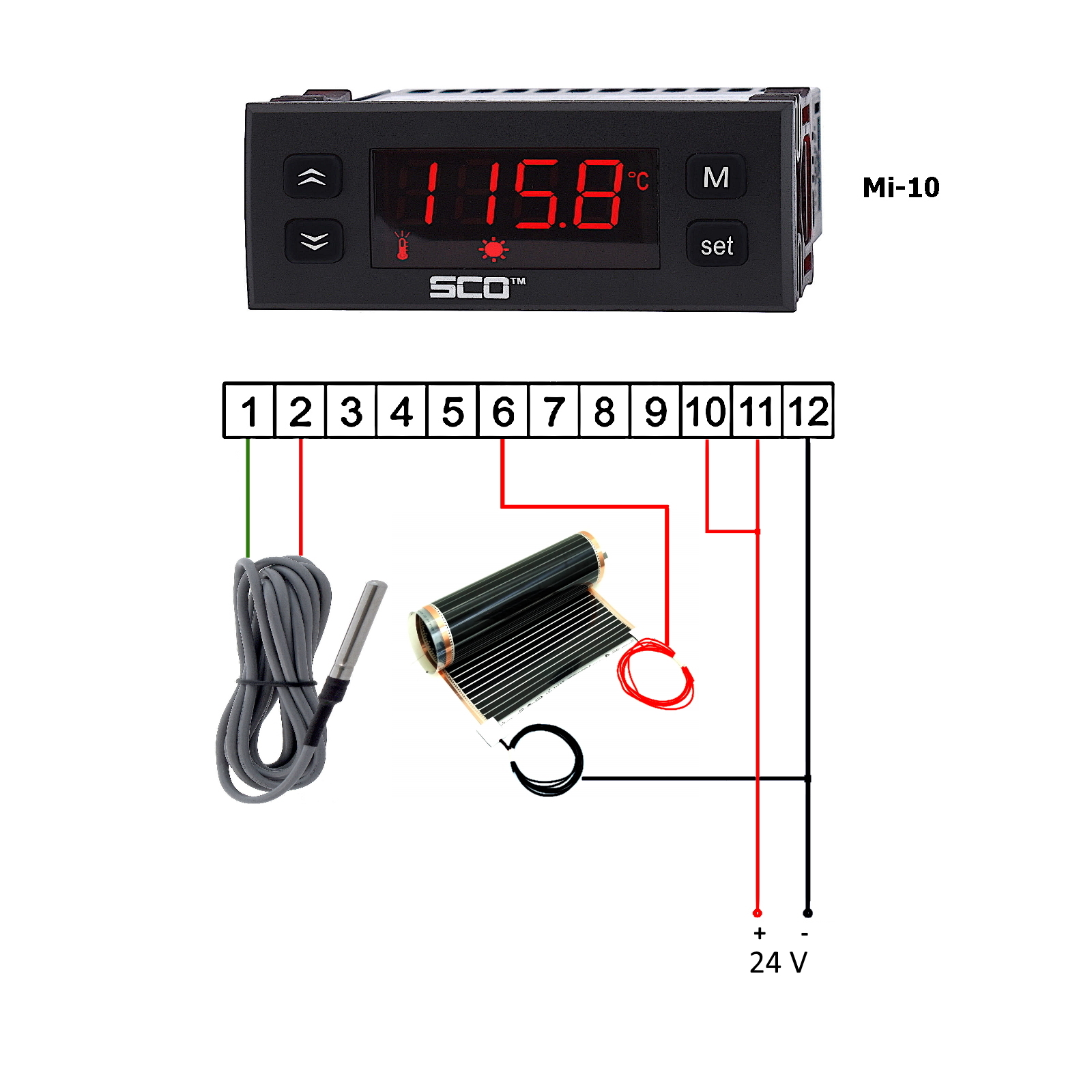
Mi-10 Thermostat 24V DC (Art.Nr. 603)
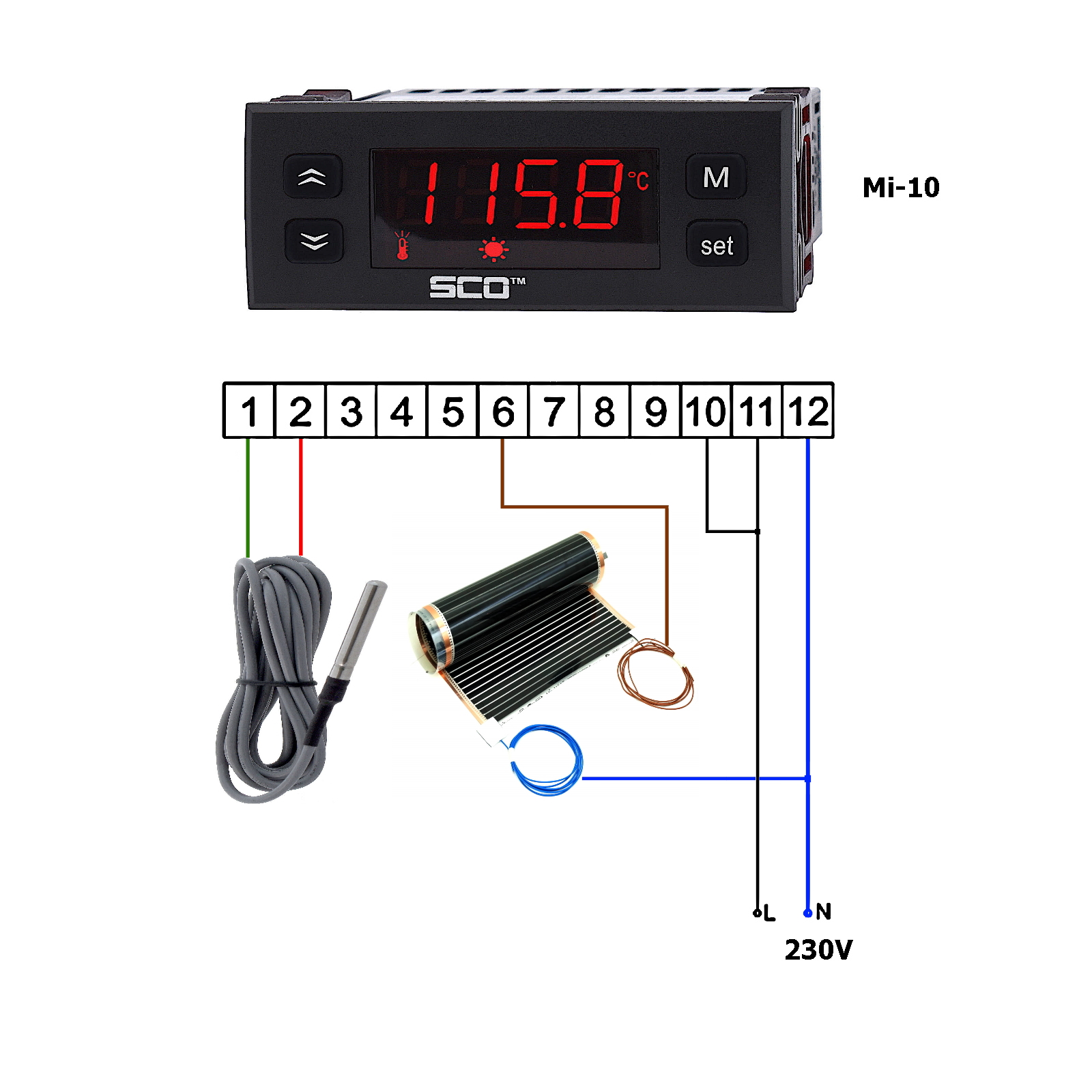
Mi-10 Thermostat 230V AC (Art.Nr. 812)
If you have already made any settings, we recommend that you first reset the ETO2 ice and snow melt control to the factory state.
This is done under Setup → Factory Reset → Reset. Then restart the unit via Exit → Restart.
After the restart, select the following settings:
- Celsius
- Sensor 1: ETOG
- Sensor 2: OFF
- Outdoor Sensor: OFF
- Application: ELECTRIC 1-ZONE
In this operating mode, all 3 relays are always switched through when the switching thresholds are reached.
The display shows "ZONE 1 HEAT" with "ON" and "ZONE 2 HEAT" with "OFF".
An external switch (potential-free) can be connected to terminals 33+34 to set the ETO2 ice and snow melt control to standby mode.
An external push-button (potential-free) can be connected to terminals 35+36 to trigger manual heating. The duration of the manual heating depends on the time set in the menu for "Afterrun time, zone 1" or "Afterrun time, zone 2".
The position of the thermostat should be in a freely accessible place and, if possible, not be exposed to direct sunlight. A cold outside wall should also be avoided if possible.
The NTC floor sensor is a temperature-dependent resistor. The polarity does not matter when connecting to the terminals provided for this purpose.
We recommend always installing the floor sensor in a corrugated tube / empty tube so that it can be easily replaced in case of damage. The empty conduit has a diameter of approx. 16mm. Appropriate recesses must be chiselled out in the wall and floor.
The sensor itself should protrude at least 10cm on or under the heating film so that the temperature can be measured correctly. If a heating mat is used instead of a heating film, the sensor should be positioned between two heating wires. Here too, the sensor should protrude at least 10cm into the heating area.
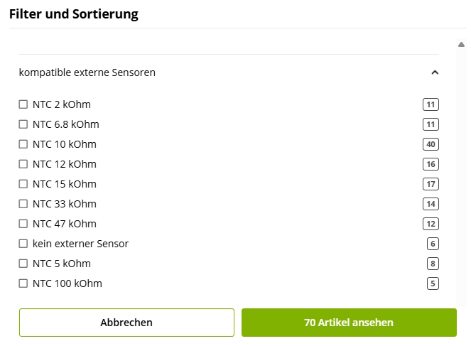
In our heating control product category, you will find helpful filter and search functions that allow you to search specifically for thermostats that match your existing floor sensor.
Simply enter the NTC sensor type or the resistance value of your sensor - you will then only be shown compatible devices. This allows you to quickly and easily find the right controller for your system.
A potential-free switching contact is a switching output that is not live. This is comparable to a standard light switch to which no cables are connected.
A potential-free switching contact offers the advantage that a wide variety of consumers can be connected. For example, devices with low voltage such as 12V / 24V / 36V or 230V mains voltage can be switched (provided the appropriate voltage source is available). In addition, a potential-free switching contact can also be used as a signalling contact, e.g. for a higher-level control system.
For our thermostats that have a potential-free switching contact, you will find a suitable connection diagram in the online shop and in the corresponding operating instructions.
Yes, normally closed actuators (NC) can be connected to the thermostat. Actuators with 230V voltage can be connected directly, for actuators with other voltages (e.g. 12 or 24V) a corresponding power supply unit is required.
With NC actuators (de-energised closed), the actuator is energised to open and with NO actuators (de-energised open), the actuator is energised to close.
The KTY semiconductor sensors (149300 remote sensors) from Gira have different resistance values compared to conventional NTC sensors with 10kOhm or 12kOhm, for example. Gira has therefore published a resistance table for this.
5 °C - 85.27 Ohm
10 °C - 66.78 Ohm
15 °C - 52.33 Ohm
20 °C - 41.27 Ohm
25 °C - 33.00 Ohm
30 °C - 26.28 Ohm
35 °C - 21.13 Ohm
40 °C - 17.08 Ohm
45 °C - 13.84 Ohm
50 °C - 11.27 Ohm
Suitable replacements are the thermostats MCD4, MCD5, OCD4, OCD5, MWD5 and OWD5 from the manufacturer OJ Electronics. In addition to the common NTC sensors, these can also be operated with other sensor types. To do this, the sensor type must be selected as "User-defined" in the technical settings and the resistance values of the sensor at 5 °C, 20 °C, 25 °C and 30 °C must be entered.
To the thermostats from OJ Electronics
No, normally closed actuators (NC) of an underfloor heating system and many boilers and heaters can also be connected to the thermostat. Please check the manual of your heater beforehand to see if it has a control input for a thermostat.
Normally, these units have a control input for an external thermostat. However, you must pay close attention to whether this control input must be switched via a potential-free switching contact, i.e. without mains voltage applied, or whether it can be provided directly with mains voltage. You will find precise information on this in the manual of your heater. If anything is unclear, a qualified electrician should be consulted for assistance.
Other products
When regulating pumps/motors, it is important to note that the starting/inrush current is many times higher (7 to 10 times) than the value stated on the unit’s rating plate.
The inrush current must therefore be determined first to ensure that the dimmer is not overloaded.
Furthermore, no devices with start-up capacitors or other upstream electronics must be connected to the power controller.
Our power controller operates using phase-angle control, which is suitable for resistive or inductive 230V AC loads. The maximum connected load of the respective power controller must be observed.
When the desired temperature is reached, only the heating element of the Ballu BKX electric fan heater is switched off. The fan continues to run to ensure optimum heat distribution in the room air.
Order
If you registered when placing your order and thus created a customer account, you can view the status and all information relating to your orders in your customer account.
There you can also download the corresponding invoices in PDF format. To do this, go to the order overview and click on the eye icon next to the desired order. Then click on the green PDF icon or the order number next to it.
You will also find the link to the respective shipping provider's tracking service here.
We also automatically send invoices to the email address you provided after your order has been shipped.
If you registered when placing your order and thus created a customer account, you can view the tracking number in the order details for the respective order in your customer account.
To do this, go to the order overview and click on the eye icon next to the desired order. You will then find a link under ‘Tracking’ that will take you to the respective shipping provider's tracking page.
If you registered when placing your order and thus created a customer account, you can view the status and all information about your orders in your customer account.
Would you like to place an order with us as a public institution or educational establishment, but the payment methods offered cannot be implemented due to regulatory guidelines? We can help here too! Pay conveniently by open invoice, within 14 days without deduction.
Please send us a list of the desired items, as well as your official address and the delivery address, so that we can enter your order manually.
Due to the fast-paced nature of online retail, we are unfortunately unable to offer product catalogues or price lists in printed form. All products on offer, including detailed descriptions, technical data and, where applicable, instructions and data sheets, are available online.
Of course, we are also happy to send your order to a different address or a parcel station/post office.
Simply enter the desired address in the shopping basket under billing and delivery address after removing the tick from ‘Delivery address corresponds to billing address’.
Information about delivery to Packstation:
- For delivery to a packing station, enter the address details for the delivery address as follows.
Fields First name Last name = Your first name and last name
Field Street = Only the word ‘Packstation’
Field House number = The number of the Packstation
Field Address supplement = Your postcode from your DHL customer account
Fields Postcode and Town = Postcode and town of the Packstation - Deliveries to packing stations are only possible for items with cardboard dimensions of at least 15x11x1cm and at most 75x60x40cm. We therefore ask you to provide a different delivery address for larger items or quantities if possible.
Information about delivery to a post office branch:
- For delivery to a post office branch, enter the address details for the delivery address as follows.
Fields First name Last name = Your first name and last name
Field Street = Only the word ‘Post Office’
Field House number = The number of the post office
Field Address supplement = Your postcode from your DHL customer account
Fields Postcode and Town = Postcode and town of the post office
If you have not received an order confirmation by email, please check your spam folder first.
If the confirmation is not in your spam folder, please check the email address provided in your customer account again for any typos that may have crept in.
If the email address is correct, we must unfortunately assume that the order process was not completed correctly or in full. We will be happy to check whether an order has been received. Please contact our support team by telephone on +49 (0)4941 6971930.
After placing an order via our online shop, you will immediately receive an order confirmation by email to the address you provided.
Once we have received your order, it will be automatically processed and shipped within the time specified for the item or under Payment and Shipping. When your order is shipped, you will automatically receive a shipping confirmation including a link for tracking your shipment and an invoice in PDF format by email.
Didn't receive an order confirmation?
Please check your spam folder first. If the confirmation is not in your spam folder, please check the email address provided in your customer account again for any typos. If the email address is correct, we unfortunately have to assume that the order process was not completed correctly or in full. We will be happy to check whether an order has been received. Please contact our support team by telephone on +49 (0)4941 6971930.
If you have created a customer account, you can create one or more wish lists.
To add products to a wish list, simply click on the heart icon next to the respective product.
To share a wish list, click on the button next to ‘Your wish list is currently not public’ in the desired wish list. You will now receive a link to your wish list that you can share. Alternatively, you can click on the letter icon behind the link to send the wish list directly by email to the desired person(s).
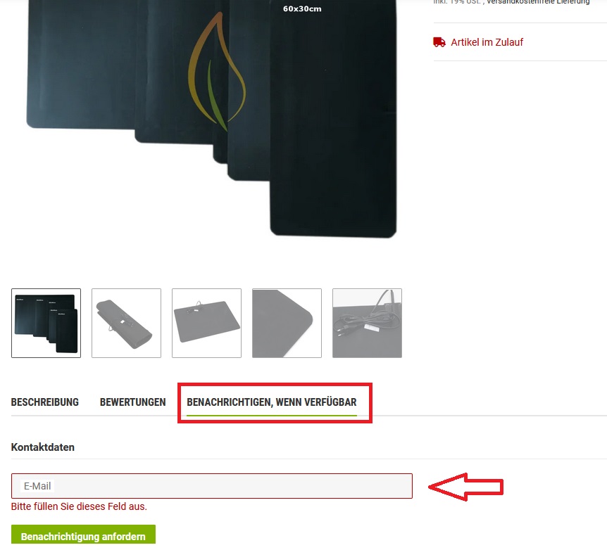
In this case, we recommend using the ‘Notify me when available’ function. You will then automatically receive an email when the item is available again and can conveniently order it via our online shop.
We naturally offer shipping to many countries.
You can find out which countries we deliver to directly in your shopping basket under ‘Calculate shipping costs for current basket contents to’ or under Payment and Shipping.
Rate an item:
If you would like to review a purchased item, please log in with your access data first. Then either call up the item directly or via the list of items for one of your orders.
To submit your personal review, click on ‘Reviews’ below the images on the item details page and then on ‘Rate item’.
Rate Mi-Heat as a company:
Would you like to rate us as a company? We would be delighted to receive your Google review. If you gave us permission to contact you regarding a review when placing your order at the end of the shopping basket, you will automatically receive a reminder email.
Your feedback is important to us and shows us what we can do even better.
At Mi-Heat, there is no minimum order value – after all, there are also small projects.
You can find an overview of all payment options on the Payment and Shipping page.
Shipping costs vary depending on the country of delivery and may depend on the shipping weight of the goods ordered. You can find a detailed overview on our Payment and Shipping page.
The protection of your data is our top priority. We collect and process personal data exclusively in accordance with the applicable data protection regulations. You can find our detailed privacy policy here.
Our general terms and conditions (GTC) contain all important information regarding contract conclusion, delivery, payment and other legal aspects. You can view the complete GTC here.
Yes, we offer an Adcell affiliate partner programme. Benefit from our expertise and our high-quality range of heating systems. Whether you are an affiliate, influencer, private individual or operator of a commercial website, you have come to the right place. You can find all the information you need here.
Our solutions are suitable for a wide range of business partners, including companies and small businesses in various industries. Potential partners include:
- Architectural/planning offices
- Energy consultants
- Craft businesses
- Electrical industry
- Specialist, wholesale and online retailers
- and many more
If you are interested in a distribution partnership and your products or services complement ours, please do not hesitate to contact us. We look forward to growing together and offering our customers the best solutions.
You may cancel your order within the statutory cancellation period. Detailed information on your right of cancellation and the cancellation form can be found here. Please send us your cancellation in writing.
If you have created a customer account, the last shopping basket that was not ordered will be saved automatically.
This means that you can simply access your previous shopping basket after logging in again.